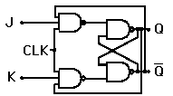
Clocked Set-Reset Flip-flop

| Example Output |
When the signal line S goes high, the other line to the NAND gate from the pulse steering circuit must also be high for it to generate a low output. Likewise, a clock pulse must have the reset NAND gate high to receive a high RESET pulse. Therefore all transitions are synchronized to the clock.
| Set-reset Flip-flop | NAND-gate Latch |
Electronics concepts
Digital circuits
| HyperPhysics*****Electricity and magnetism | R Nave |


